Variable valve timing (VVT) engines have become rather common in the last decade. Different versions of VVT technology exist, but the version this article will focus on is using a phaser to manipulate camshaft position and, therefore, valve timing.
(See Figure 1)
Phasers can be found just on the exhaust cam or on both the intake and exhaust cams. The alteration of camshaft position changes the cam centerline and the lobe separation angle between intake and exhaust cams. This allows engineers to improve fuel economy and power while continuing to meet emissions standards.
VVT presents additional diagnostic challenges and repair opportunities to the service industry including new trouble codes, so if you are not familiar with these units, it’s time to advance your diagnostic readiness by examining the VVT system, its controls and operation.
Since motor oil is the hydraulic medium that makes VVT work, it is imperative that engines are filled to the correct level with clean motor oil of the proper viscosity. Low oil level or the wrong viscosity can result in system slow response codes such as P000A or P000B and possible drive complaints including an illuminated MIL.
Oil pressure is another critical factor in the VVT system. As bearings wear and develop clearance, oil pressure will be affected. VVT engines are machined with additional oil galleys and are equipped with one or more fine mesh screens to prevent debris from entering components. If these screens need to be replaced, the entire engine may need to be disassembled.
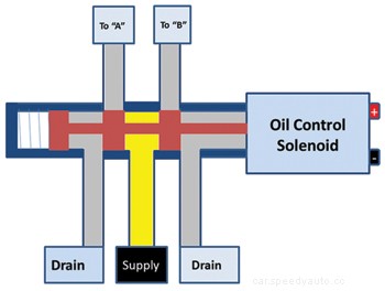
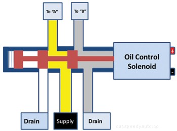
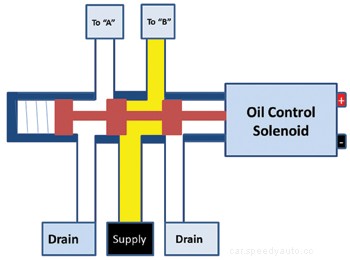
VVT engines commonly have sensors that monitor oil pressure and oil temperature and are a part of system control strategy. The major control component in camshaft phasing is the oil control valve (OCV). The OCV is a spool valve, much like those found in automatic transmissions, that acts as an oil control device.
(See Figures 2,3,4,and 5)
It determines which ports receive pressurized oil and which are vented. The PCM (powertrain control module) duty-cycles a solenoid that alters valve position. Pressurized oil travels through the OCV to one of the camshaft bearing journals.
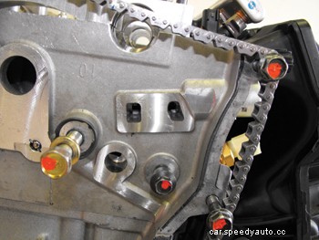
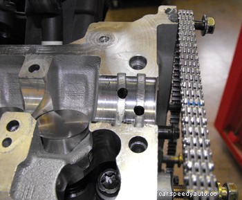
(See Figure 6)
It then flows though passageways inside and toward the front of the camshaft. Once at the nose of the camshaft, oil enters the camshaft-phaser.
*It is not recommended to disassemble the phaser as they are only sold as an assembly.*
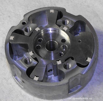
The phaser is a two-piece mechanism comprised of the rotor and the phaser body. The phaser body is physically bolted to the camshaft sprocket and the rotor is connected to the camshaft using a dowel pin.
(See Figure 7)
The two pieces can move about 20° (40 crankshaft degrees) independently of each other. Ports inside the phaser direct oil in or out of eight chambers. The chambers are grouped into two sides, A and B. As one group receives pressurized oil, the others are vented which provides the force necessary to move or hold the rotor relative to the phaser body. Oil seals fit into machined grooves of the rotor to provide a tight seal between the chambers.
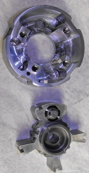
Vented oil from the phaser ports travels back through the camshaft, the cam bearing ports, through the oil control valve and then drains into the front timing cover. Inside the phaser, the spring-loaded lock pin on the rotor engages into the phaser body to lock the two pieces together. This prevents noise and potential wear on engine start. Oil pressure is required to disengage the lock pin.
(See Figure 8)
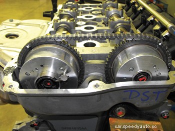
The locked phaser positions on the 2.4L Chrysler engine disassembled in the photos are full retard on the intake and full advance on the exhaust. Because of the clockwise rotation when viewed from the front of the engine, the exhaust rotor receives additional assistance from a spring to reach the full advance position. When in the default position there is no valve overlap.
Electrically, the OCV solenoid has two terminals that connect to the PCM which provides duty-cycle control. The resistance of the solenoid and the side the control is on varies between manufacturers. As part of a cleaning and diagnostic strategy, OCV solenoids are typically cycled upon ignition run mode. Regardless of control specifics, the PCM monitors solenoid circuits for faults including opens, shorts to ground or shorts to voltage.
(See Figure 9)
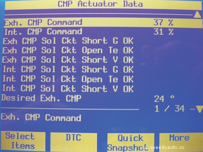
OCV solenoid circuit fault codes include P0010 and P0013. Besides retrieving trouble codes, scan tools are useful to monitor desired versus actual camshaft position and may also be equipped with helpful actuator tests and cleaning routines.Crankshaft position sensors (CKP) and camshaft position sensors (CMP) are used by the PCM to determine camshaft phasing functionality. CMP tone rings or trigger wheels are usually connected to the cam itself rather than the sprocket. When the PCM commands the OCV solenoid to advance or retard, CMP patterns are compared to CKP patterns to determine if the command is carried out. A variance or error value is calculated. Once the variance reaches a certain point, a fault is declared. These include DTCs P0011 and P0014, which are target performance errors. This also makes it more important than ever that camshaft timing be set correctly during timing chain or belt service. A CKP or CMP sensor fault can also cause the PCM to disable or limit VVT operation.
With vehicle manufacturers having to use every tool at their disposal to meet sharply increasing CAFE (corporate average fuel economy) requirements, it is likely we will see more VVT-equipped engines. These systems are well engineered and have proven to be reliable. That being said, heat, age, wear and lack of maintenance are likely reasons to cause eventual failures. Looking at these components, including the fine mesh screens, provides great incentive to keep oil changed regularly. Hopefully this look at the system components, controls and operation leaves you ready in time to service the growing number of VVT-equipped vehicles.
